 |
 |
|
QY65H531 Characteristics
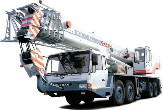
(1) This type of truck crane, one of the classic products in the same trade, has earned a good reputation from the customers. (2) The crane adopts a standard-type and self-made special-purpose chassis with a full-width driver°Įs cab. The chassis drive type is 8°Ń4. (3) The crane adopts WEICHAI Steyr engine which is specially developed for those cranes that often travel at low speed. This kind of engine not only can produce large output torque when it starts and increase the traveling speed quickly, but also has excellent starting performance and good gradeability. (4) The crane is equipped with 9-speed gearbox which changes gear smoothly and is of simple structure and makes maintenance convenient. (5) The crane is fitted with a 41.5m long hexagon-section boom which is made of high-strength steel, so the boom has strong resistance to bending and torsion. The distinctively-designed circular arc sliding block (having obtained a national patent) makes the stress distributed more evenly, the load carrying capacity stronger, and the adjustment easier. The local rigidity in boom supporting point is good, which has improved the lifting capacity on boom with same thickness and achieved the goal of greater lifting capacity on lighter boom.
(6) The boom applies an arbitrary telescopic type which can improve the stability of crane when it works with large working radius. (When boom telescopes in different sequence, the position of boom°Įs centre of gravity is adjusted accordingly.) (7) The unique manual full proportional control incorporates the advantages of traditional lever control and electric-hydraulic pilot control. It not only reserves the merits of safety & reliability of original control structure and low maintenance cost, but also realizes that the working speed of actuating mechanism is only proportional to the opening degree of control valves, rather than affected by the load. Furthermore, it has improved the speed-regulation performance. (8) The slewing mechanism has the functions of protecting the crane automatically when the crane is overloaded, reducing the impacts, and activating hydraulic brake when the hydraulic control valve is in neutral position as well as free swing. In addition, it can automatically make boom, wire rope and lifted load slew simultaneously, and minimize the sway of boom and load while the crane starts or stops quickly, and accelerates or decelerates slewing. (9) The outrigger beam boasts such advantages as large outrigger span and outstanding stability. (10) The crane is equipped with high-quality load moment limiter which has such advantages as great precision and complete information shown on the display. In this way, the safe lifting operation can be guaranteed. |
|
Table of Main Technica Performance and Specifications |
Item |
Value |
Remarks |
|||
Working performance specification |
Max. rated total lifting capacity kg |
65000 |
|||
Max. load moment of basic boom kN.m |
2160 |
||||
Max. load moment with max. main boom length kN.m |
1024 |
||||
Max. lifting height of basic boom m |
12 |
||||
Max. lifting height of main boom m |
41 |
Deformation of boom is not taken into consideration. |
|||
Max. lifting height of fly jib m |
56 |
||||
Working speed |
Max. speed of single rope on main winch m/min |
140 |
The 4 th layer of drum |
||
Max. speed of single rope on auxiliary winch m/min |
120 |
The 2 nd layer of drum |
|||
Derricking time of boom s |
65 |
||||
Telescopic time of boom s |
100 |
||||
Slewing speed r/min |
0 °ę 1.8 |
||||
Traveling specification |
Max. traveling speed km/h |
71 |
|||
Max. gradeability % |
30 |
||||
Min. turning circle diameter m |
23.7 |
||||
Min. ground clearance mm |
250 |
||||
Limits for exhaust pollutants and smoke |
Comply with related standards |
GB3847-2005 |
|||
Oil consumption per hundred kilometers L |
55 |
||||
Mass specification |
Deadweight of crane in traveling condition kg |
45000 |
|||
Complete vehicle kerb mass kg |
44800 |
||||
Front axle load kg |
19000 |
||||
Rear axle load kg |
26000 |
||||
Dimension specification |
Overall dimensions(L °Ń W °Ń H) mm |
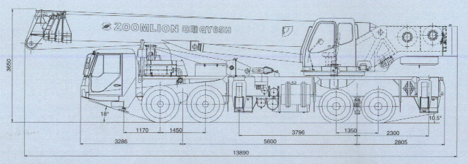
13890°Ń2750°Ń3650 |
|||
Base on outriggers m |
5.95 |
||||
Distance between outriggers m |
7.00 |
||||
Main boom length m |
11.2 °ę 41.5 |
||||
Main boom angle °„ |
-2 °ę 80 |
||||
Fly jib length m |
9, 15 |
||||
Offset angle of fly jib °„ |
5 , 30 |
||||
Chassis |
Model |
ZLJ5454 |
Feature No: ZLJ5454H3 |
||
Class |
II |
||||
Engine |
Model |
EuroĘů(WP10.375) |
|||
Rated power kW/r/min |
276/2200 |
||||
Max. output torque |
1460/1200 °ę 1600 |
||||
Working Radius (m) |
Boom(extend cylinder I firstly and completely with auxiliary counterweight) |
Boom(extend cylinder II firstly and completely with auxiliary counterweight) |
Boom(extend cylinder firstly but not completely with auxiliary counterweight) |
boom angle (°„) |
boom+jib |
||||||||||||||||
|
With outriggers fully extended in side & rear working erea |
With outriggers fully extended in side & rear working area |
With outriggers fully extended in side & rear working area |
41.5m+9m |
41.5m+15m |
|||||||||||||||||
|
Boom length |
Boom length |
Boom length
|
offset angle of jib |
offset angle of jib |
|||||||||||||||||
11.2m |
15.00m |
18.77m |
26.35m |
33.92m |
41.5m |
11.2m |
18.77m |
26.35m |
33.92m |
41.5m |
11.2m |
18.77m |
26.35m |
33.92m |
41.5m |
5°„ |
30°„ |
5°„ |
30°„ |
||
3.0 |
65000 |
65000 |
65000 |
4000 |
2150 |
2400 |
1000 |
||||||||||||||
3.5 |
61500 |
61500 |
61500 |
80°„ |
3800 |
2050 |
2180 |
1000 |
|||||||||||||
4.0 |
54000 |
46000 |
36000 |
54000 |
54000 |
78°„ |
3500 |
1950 |
1920 |
1000 |
|||||||||||
4.5 |
48000 |
43000 |
35500 |
48000 |
48000 |
76°„ |
3150 |
1900 |
1820 |
1000 |
|||||||||||
5.0 |
46500 |
40000 |
34000 |
21500 |
46500 |
22000 |
46500 |
22000 |
74°„ |
2850 |
1850 |
1690 |
1000 |
||||||||
5.5 |
40000 |
35000 |
32000 |
21500 |
40000 |
22000 |
40000 |
22000 |
72°„ |
2700 |
1800 |
1530 |
1000 |
||||||||
6.0 |
38000 |
33000 |
30000 |
21500 |
38000 |
22000 |
38000 |
22000 |
70°„ |
2550 |
1750 |
1380 |
900 |
||||||||
6.5 |
33500 |
28000 |
28500 |
21000 |
16500 |
33500 |
21000 |
31000 |
21000 |
68°„ |
2450 |
1650 |
1230 |
800 |
|||||||
7.0 |
29000 |
26000 |
27000 |
19000 |
15500 |
29000 |
21000 |
16500 |
28000 |
20000 |
16500 |
66°„ |
2150 |
1400 |
1080 |
700 |
|||||
8.0 |
23500 |
21000 |
23000 |
17000 |
14500 |
9000 |
23500 |
19000 |
15500 |
22000 |
19000 |
15500 |
64°„ |
1850 |
1150 |
950 |
600 |
||||
9.0 |
17500 |
17000 |
17000 |
15000 |
13000 |
8800 |
17500 |
15500 |
14500 |
9000 |
9000 |
16000 |
15000 |
14500 |
9000 |
9000 |
62°„ |
1550 |
1000 |
830 |
|
10.0 |
12800 |
13500 |
13000 |
12000 |
8300 |
13000 |
13000 |
8800 |
8800 |
12000 |
13000 |
8800 |
8800 |
60°„ |
1350 |
850 |
700 |
||||
11.0 |
11000 |
11500 |
10000 |
11500 |
8000 |
11500 |
11500 |
8300 |
8300 |
11500 |
11500 |
8300 |
8300 |
58°„ |
1100 |
700 |
600 |
||||
12.0 |
9000 |
8500 |
10500 |
7500 |
8800 |
10000 |
8000 |
8000 |
9000 |
9000 |
8000 |
8000 |
56°„ |
950 |
550 |
500 |
|||||
13.0 |
7200 |
7500 |
9200 |
7300 |
7500 |
8500 |
7500 |
7500 |
7200 |
7800 |
7500 |
7500 |
54°„ |
750 |
|||||||
14.0 |
5800 |
6500 |
7500 |
6500 |
6500 |
80000 |
7300 |
7300 |
5800 |
7000 |
7300 |
7300 |
52°„ |
||||||||
15.0 |
5500 |
6500 |
6400 |
7000 |
6800 |
6500 |
6500 |
6500 |
6500 |
50°„ |
|||||||||||
16.0 |
4500 |
5000 |
5300 |
6800 |
6600 |
6400 |
5500 |
6200 |
6400 |
||||||||||||
18.0 |
3200 |
3800 |
4500 |
5000 |
5200 |
5300 |
4500 |
5000 |
5300 |
||||||||||||
20.0 |
2500 |
2900 |
3500 |
4000 |
4000 |
4500 |
3200 |
3800 |
4500 |
||||||||||||
22.0 |
2200 |
2500 |
3500 |
3500 |
2500 |
2900 |
3500 |
||||||||||||||
24.0 |
1800 |
3200 |
2500 |
2200 |
2500 |
||||||||||||||||
26.0 |
1200 |
1800 |
1800 |
||||||||||||||||||
28.0 |
1200 |
1200 |
|||||||||||||||||||
|
Critical boom angle |
25°„ |
35°„ |
42°„ |
25°„ |
35°„ |
42°„ |
25°„ |
35°„ |
42°„ |
||||||||||||
|
Note:1.Above working condition is when the outriggers extend completely.It is forbidden to lift a load without the support of outriggers. 2.The rated total lifting capacities above the thick line listed in the table are determined by the structural strength,and the others are determined by the stability of the complete vehicle. 3.Set up the 5th outrigger and then it is suitable for 360°„operation. 4.The rated lifting capacity in above table is the maximum permitted lifting capacity,which includes the weight of hook (main hook's weight is 565kg and auxiliary hook's weight is 100kg). 5.The working radius given in the table is the horzontal distance from the table,the larger value should be taken to ascertain lifting capacity. 6.When actual boom length and working radius are between two values in the table,the larger value should be taken to ascertain lifting capacity. 7.When boom works while that jib has been extended, its rated lifting capacity should be subtracted by not only load handling device's weight,but also jib's weight 2000kg. 8.The min.wire rope falls(the number of wire rope) of hook should be determined under the condition that the lifting capacity of single wire rope for jib is 1,and the standard rope falls of wire rope for various boom lengths refer the following table. 9.The boom angle should not be smaller than the min.Boom angle with various boom lengths.otherwise the crane will overturn even though it does not lift a load. When the Boom length is more than the value in the table,the min.Boom angle should be determined by the longer boom length. 10.The complete vehicle with auxiliary counterweight is only for lifting operation. It is forbidden to travel with auxiliary counterweight, otherwise it is very dangerous! |
 |
New sliding design for bracing support, side hydraulic luck |
Side hydraulic luck, avoiding heavy crash during the operation, ensures security. |
|
 |
Anti-slew steel wire |
Longevity of service for the anti-slew steel wire, ensures the security of the lifting. |
|
 |
Moment Limiter and Display |
Automatic moment limiter has the function of self testing and alarming. |
|
 |
Major boom head and slider |
1°ĘHexagon major boom adopts low alloy and high strength structure steel |
|
 |
Hydraulic Motor |
1°ĘSupercharged inter-cooled engine, capable for working at place over 4500 meters altitude. |
| Note: All specifications on our web-site are subject to technical modifications without notice. |